Flow rate is a critical parameter for monitoring and controlling the operational conditions in a variety of industries, laboratories and utility services. It can be linked to asset management, keeping the fluid in motion or even simple tank balancing. In fact, some applications require conducting accurate flow rate measurements to maintain product quality and ensure the health and safety of workers around the tank facility as inaccurate flow rate measurements or failing to take such measurements can cause serious or disastrous results. Hence, to accurately and effectively measure flow rate in incompressible fluids such as water, differential pressure transducers are commonly used.
Read this guide to understand how pressure transducers work
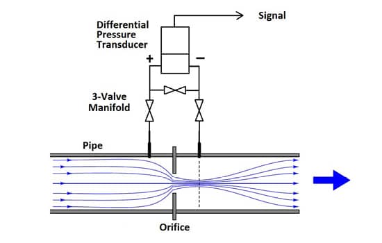
A differential pressure transducer acquires the differential pressure of a closed system by calculating the difference of applied force at two measurement points against pre-defined application parameters. As in the case of a water pipe, a differential pressure flowmeter such as an orifice plate is used, which introduces a constriction in the pipe to create a pressure drop across the flowmeter. The orifice plate is simply installed in the pipe between the flanges. As the fluid passes through this plate, a pressure drop is developed across the orifice plate that routes from the upstream side to the downstream side. As shown in the figure below, the orifice is installed in the water pipe in such a way that the upstream side of the orifice, which will have the higher pressure, is connected through a three-valve manifold to the + port of the pressure transducer. Similarly, the downstream portion of the orifice is connected to the – port. The three-valve manifold protects the pressure sensor from overpressure which can be inflicted during installation.
The Calculation of Flow Rate
The above fluid flow measurement system is based on Bernouili’s principle which states that the pressure drop across the constriction is proportional to the square of the flow rate. The flow rate is derived from the measured readings of pressure drop with the help of physical equations comprising a number of variables with different engineering units. These variables include orifice geometry, pipe dimensions, fluid viscosity and fluid density. To get to the final value of flow rate, extensive calculations and iterations are required, given the number of terms and the conversion factors involved for each of the variables. To do so, a simple equation is devised from different pressure drops readings and calculating flow rate using online calculators. This equation aims at converting the pressure transducer output signal into engineering units of flow.
To formulate the equation, let’s consider an example to replicate the fluid flow measurement system. Consider a 6 inches ID pipe suitable for pumping water at the rates of 200 to 600 gallons/min. An orifice plate with a diameter of 4 inches is installed in this pipe. The allowed fluid density of water and its viscosity are 8.345 lbs/gal and 1 centipoise respectively. To this setup, a series of flow rate calculations for pressure drop readings taken from pressure transducers of different calibrations were recorded in the table below.
Pressure drop in In H2O
| Differential Pressure (in H2O) | Signal (in Vdc) | Flow Rates |
| 100 | +5.00 | 640 |
| 50 | +2.50 | 453 |
| 25 | +1.25 | 321 |
| 10 | +0.50 | 203 |
Based on the relationship between the above values of flow rate and differential pressure, the following equation can be derived, which is nothing but a simplified version of Bernoulli’s Equation.
Q = k √ΔP
Q = Flow rate
K = orifice coefficient
ΔP = Pressure drop
To verify this equation, the value of k can be calculated using the first entry by dividing the flow rate by the square root of differential pressure. The value of k thus obtained can be used to verify other entries by multiplying their pressure drop value by k or by dividing flow rate by k. Thus, the value of k can be verified across the full calibrated range of the pressure transducer.
Similarly, for signal in Vdc, the equation can be given as :
Q = k √ΔVdc
If Signal is in mA
The given system can employ a pressure transducer signal of 4 to 20 mA. However, in this case, 4 mA must be subtracted from the signal reading due to the offset of 4 mA at zero differential pressure. Let us check the calculation using the same readings of differential pressure and flow rates, but with the reading of the signal in mA.
| Differential Pressure (in H2O) | Signal (in mA) | Flow Rates |
| 100 | 20.00 | 640 |
| 50 | 12.00 | 453 |
| 25 | 8.00 | 321 |
| 10 | 5.60 | 203 |
The revised formula for mA signal reading will be:
Q = k √(mA – 4)
Now, to verify the equation, the value of k can be calculated from the first entry of the given table. This value can then be used to calculate the value of Q or the value of mA reading.
The above-given equations are generally able to yield flow rates accurate to about 1%, depending on the various factors that may affect the flow through the orifice. In fact, using an orifice as a flowmeter is considered to be most accurate for pipes greater than 2 inches ID. The system based on orifice plate and pressure transducer is cost-effective and low maintenance and provides reasonably accurate results over a wide range of pipe sizes, liquid types and flow rates. Other fluid flow measurement methods involve using paddle wheels, turbine meters, electromagnetic types and many other tools.