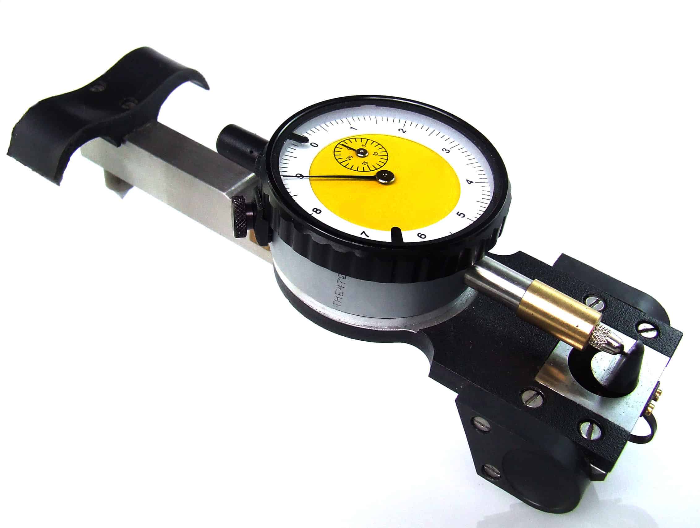
A DEMEC Demountable Mechanical Strain Gauge has advantages of providing accurate, reliable and cost-effective strain measurement over other products. However, the desired accuracy can only be obtained via precision manufacture and care in the use of the instrument. 200 strains/hr can be measured at an accuracy of ±5 x 10^(-6) ɛ under most laboratory test conditions. Great accuracy is achieved by using the gauge in its ideal horizontal position with readings lying within a small range on the dial. The DEMEC strain gauge uses a lever and dial/digital indicating gauge arrangement mounted on an Invar Main Beam, and is easy to use. The choice of material for the main beam and the reference bar is due to the requirement for the metal with low coefficient of thermal expansion. Care is required in mounting the reference/locating discs onto the measuring surfaces. Should concrete under temperature change during the testing, a concrete dummy bar is required in order to eliminate the temperature effect on the instrument.
The DEMEC strain gauge has two locating points, one fixed and one moveable measuring at the gauge length. Our DEMEC gauge is supplied completely with reference and setting bars, a pack of 100 standard locating discs are also provided.
The Demountable Mechanical Strain Gauge developed as a reliable and accurate way of taking strain measurements at different points on a structure using a single instrument. Standard gauge lengths are from 100mm to 500mm, while length of up to 2000mm available on request. The DEMEC strain gauge is ideal for use on many types of structure for strain measurement and crack monitoring. The digital DEMEC strain gauge incorporates a digital indicator with a resolution of 0.001mm, zero set, pre-set and output for Statistical Process Control (SPC) systems. The indicator can be connected to a data processor for recording and analysis of results. The indicator displays spindle movement digitally by means of a linear encoder and has a response speed of 1000mm/sec, and is battery operated. For more details pleases download product brochure.

 Any two rigid bodies, or two small, sensibly rigid, parts of an elastic body may exhibit six degrees of freedom relative to each other, and an instrument which is designed to connect these two parts must, in general, allow these six movements in order to eliminate internal straining of the instrument. In the instrument under discussion two virtual point connections are used between the instrument and the specimen and translational freedom between the connections is provided by a moving arm pivoting about a knife-edge and seating. The practical form of connection used is that of a cone locating into an initially cylindrical hole. Examination under a microscope shows that the first applications of the hardened cone, on the setting out bar, into the hole cause plastic deformation of the steel seating and an approximately toroidal surface is produced. The combination of cone and toroid provides a fixed centre of rotation about the x and y axes as well as the z axis for a sufficiently large range of angular movement to make the operation of the instrument satisfactory. The apex angle of the cone is 60 degrees. The 6.3mm diameter stainless steel locating discs are blanked and blind hole drilled 1mm diameter. On any gauge length the rotation of the moving arm for various concrete strains is very small so that the cosine variation error of readings is negligible in concrete. A point of considerable interest in designing the instrument is to ensure that the locating force applied by the operator is directed along the axes of the instrument points. A subsidiary frame can be provided to ensure this but it has been found that so long as the handles of the instrument are placed so that no deformation is caused by the locating force, it is not difficult to eliminate, with practice, other sources of error such as horizontal thrust and variations of the instrument from the vertical. The digital version uses the Mitutoyo 543 digital indicator. Strain measurement principle formula:
 Example1:From our original set
gauge length of 200mm and the dial gauge set at 0.000, the next dial gauge reading we take is 0.001, i.e. the indicator has moved one increment. Then the following calculation applies. a) Extension is: 0.8(nominal pivot lever ratio) x 1 (1 increment) x 0.001mm Therefore: Extension = 0.0008 mm b) Strain is calculated as follows:
Example1:From our original set
gauge length of 200mm and the dial gauge set at 0.000, the next dial gauge reading we take is 0.001, i.e. the indicator has moved one increment. Then the following calculation applies. a) Extension is: 0.8(nominal pivot lever ratio) x 1 (1 increment) x 0.001mm Therefore: Extension = 0.0008 mm b) Strain is calculated as follows: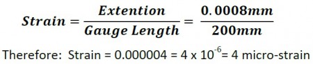 Example2:From our original set gauge length of 200mm and the dial gauge set at 0.000, the next dial gauge reading we take is 5.000. Then the following calculation applies. a) Extension is: 0.8 (nominal pivot lever ratio) x 500 x 0.001mm Therefore: Extension = 0.4 mm b) Strain is calculated as follows: