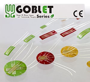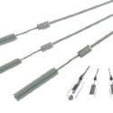
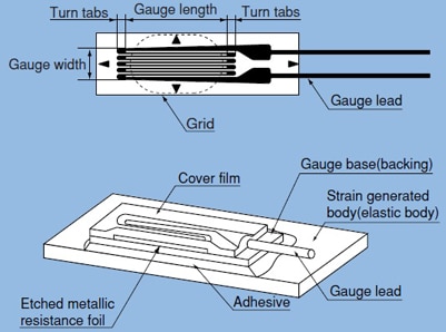
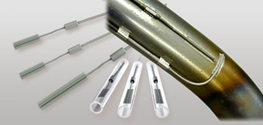
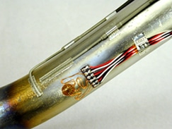
The weldable strain gauges generally have a simple construction consisting of a fine electric resistance wire or photo-etched metallic resistance foil, together with an electrical insulation base and a set of gauge leads. The AW series of weldable strain gauges are typically installed by spot-welding onto metal surfaces for use in harsh environments, such as on engines, heated turbines or field sites for long periods.
Each model has a stainless steel or inconel carrier backing and the element itself is made from a special alloy. An important feature of the weldable strain gauge series is the capability of measurement in high temperature. Both static and dynamic strain measurements can be made in temperatures of up to 800°C. Quarter bridge and full bridge constructions are available and strain limits range from 0.5% to 1.0%, depending on the specific type of strain gauge.
TML strain gauges are widely used for physical force measurements in mechanical, marine, aircraft and civil engineering as well as the fields of architecture, automotive and medical science.
Note: Each strain gauge has its limitations in temperature/ humidity, fatigue, the amount of strain, material under test and the measurement environment. These factors must be examined before a strain gauge is selected.
Operational temperature: -20℃ to+80℃
Temperature compensation range: +10℃ to +80℃
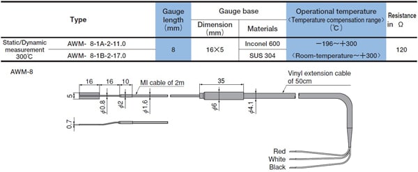
AWM-8 Quarter bridge with 3-wire system
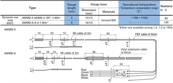
 AWMD-5, AWMD-8 (for dynamic measurement only) Full bridge
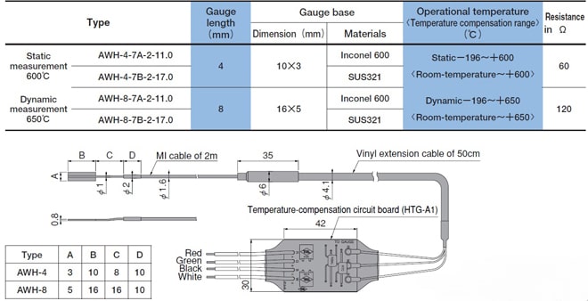
 AWH-4, AWH-8 Full bridge
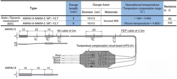
 AWHU-5, AWHU-8 Full bridge
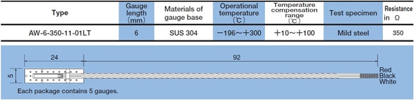
 AW-6-350-11-01LT Quarter bridge with 3-wire system
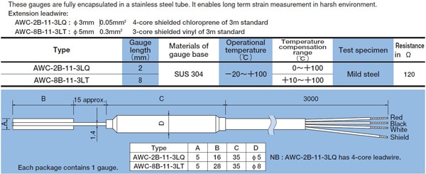
 AWC-2B-11-3LQ 1 Gauge 4-Wire system & AWC-8B-11-3LT Quarter bridge with 3-wire system

 AWMD-5, AWMD-8 (for dynamic measurement only) Full bridge
 AWH-4, AWH-8 Full bridge
 AWHU-5, AWHU-8 Full bridge
 AW-6-350-11-01LT Quarter bridge with 3-wire system
 AWC-2B-11-3LQ 1 Gauge 4-Wire system & AWC-8B-11-3LT Quarter bridge with 3-wire system
When strain is generated in a test specimen and a strain gauge is tightly bonded, the strain is relayed via the gauge base (electrical insulation backing material) to the etched metallic resistance foilpattern causing mechanical extension or shortening. As a result, alloy foil experiencesa variation in electrical resistance. This resistance of the foil change is in a defined way proportionally to the strain.
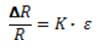
Strain measurement principle formula:
 Where,
 [Extension or Shortening] Resistance change due to strain (Ω, ohm)
 Original resistance of strain gage (Ω, ohm)
 Proportional constant also called Gauge Factor (shown on product package)
 Strain causing the resistance change (strain is measured)
The Gauge FactorK differs from metallic materials.
Strain causing the resistance change (strain is measured)
The Gauge FactorK differs from metallic materials.

Enquire Now
 Where,
 For more information,