
Today, every time a new model of airplane, automobile or a railroad vehicle is introduced, the main priority is to design its structure to be lighter and compact. This is to ensure that the structure exhibits faster running speed and less fuel consumption. However, during this process, if the required strength of the structure is not maintained, the safety of the product gets compromised. By the same token, if only the strength of the material is taken into account, the ideal weight of the product isn’t achieved and the economic feasibility gets impaired. Therefore, to maintain the harmony between safety and cost while designing the product, it is significant to know the stress borne by each material part. To determine the internal stress of a material, it is crucial to measure the strain on its surface.
The same requirement is applicable for structures such as bridges, tunnels, pipelines, roadways or dams. They are continuously exposed to harsh environmental conditions that slowly degrade their integrity. In this case, strain measurement is done as part of Health Monitoring operations for identifying any significant changes that might obstruct the usual functioning of the structure and hence develop faults.
To measure strain, several monitoring methods including ultrasonic wave propagation, acoustic emission, magnetic field analysis, X-ray radiography and sensor systems such as extensometer, accelerometer, pressure transducers and temperature sensors have been traditionally used. However, their high susceptibility to ambient noise frequency, high-cost, inaccessibility in remote areas or fragile nature made them unreliable in providing strain measurements at some points. Strain gauges have popularly been used for test and measurement operations in design studies, finite element, and modeling calculations and continuous structural health monitoring scenarios. They are inexpensive, easy to install and highly sensitive to detect the potential danger of the collapse of a structure. The strain gauge technology has been employed as a key tool for measuring fatigue and deformation in various fields such as aerospace, railways, construction, electronics, automotive, etc in a wide range of applications.
This article is entirely focussed on foil type strain gauges or electrical strain gauges. It deeply explains the fundamentals of strain gauge, features, configurations, working principles and applications.
What is Strain Gauge?
Invented in 1938, a strain gauge is used to measure stress, strain and other force-related parameters such as torque, acceleration, pressure, and vibration. These physical parameters of the structure help in ensuring the safety and efficiency of the structure. The gauge is simply bonded or glued to an object such as metal, plastic, wood or composite materials to measure surface strain. In some cases, special strain gauges can also be embedded into the objects to be tested. Measurements by strain gauges do not get affected by temperature change, hence they are suitable for long-term installation. They are easy to maintain and generally have a long operating life.

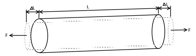
When a force is applied to an elastic material (such as steel), it generates stress which deforms the material. At this time, the material extends to a distance ΔL if the applied force is a tensile force, with L as its original length. The ratio of ΔL and L is known as strain.
By determining the value of strain, the absolute value and direction of the mechanical stress are determined. In this calculation, the value of the modulus of elasticity of the material on which strain was determined is used.
The calculation is based on Hooke’s law that defines the relationship between stress and strain. It states that the strain ε [m/m] and the stress σ [N/mm2] of a certain material are directly proportional.
σ ∝E
σ = ε⋅E
Here, E is the constant of proportionality known as Young’s modulus or the modulus of Elasticity, which is different for each material.
Characteristics of a Strain Gauge
Strain gauges are available in a wide range to enable strain measurements for all types of applications and environments. They are available in various sizes, even for applications where space is limited. Due to their compact nature, they are ideal for measuring strain in electronic components that are integrated into various devices. Along with the gauge size, various options of gauge lengths are also available for measuring different types of specimens.
One of the most important characteristics of a strain gauge is its high accuracy. A strain gauge is configured using a Wheatstone Bridge Circuit, which enables a good range of accuracies with its four forms of configurations. With any change in the strain gauge resistance of the circuit, the strain gauge produces a non-zero output voltage.
Another important feature of a strain gauge is its high-frequency response. It differs for every gauge length and the material to which the gauge is bonded.
Strain Gauge Design and Configuration
The strain gauge is typically constructed by forming a grid of fine electric resistance wire or etched metallic resistance foil on a piece of insulating material called the base or backing. The grid is bonded to the surface in the direction of the applied force and attached to this structure are the gauge leads.
The cross-sectional area of the strain gauge is minimized to reduce the negative effect of the shear. As the force is applied, the strain experienced by the test body is transferred directly to the foil grid of the strain gauge, which responds with a linear change in the electrical resistance of the gauge.
The accuracy of the measured strain highly depends on the strain gauge’s geometry, i.e. the number of grids and the positioning of grids. There are several strain gauge geometries to choose from, depending on the type of applications, the shape of the target object and the direction of the force. For a rotating structure, shear strain is measured, hence the geometry will be entirely different from the gauge used while measuring strain in a bending beam.
Linear strain gauges are designed for measuring strain in one direction only. They generally record strain in the direction in which their measuring grids are aligned. For double-sided strain measurements, a double-linear strain gauge is picked. Apart from that, there are Shear, Rosette and Chain strain gauges for determining torque, biaxial stress and strain gradient respectively. For accurate measurements, while manufacturing precision force transducers, a full-bridge strain gauge with four measurement grids is used.

Strain Gauge Working Principle
A strain gauge basically works on the principle of electrical conductance and relies heavily on a structure’s geometry. It is simply designed on the basis of the phenomenon that the length of a resistance wire is directly proportional to the resistance of the wire, as per the following equation.
R= ρ \frac{L}{A}
Here, R=resistance of the wire,
ρ=resistivity
L=length of the wire
and A= area of the cross-section of the wire
As the wire is stretched outwards, its length increases and the area of the crosssection of the wire decreases. Then, according to the above equation, the value of the new resistance will be:
Rnew=ρ(\frac{L+ΔL}{\frac{π}{4}(D-ΔD)^2})Here, Rnew is the new resistance generated due to the change in dimensions and is also called strained resistance. D is the diameter of the cross-section of the wire.
Now, in a strain gauge, when a strain is identified, it is transferred to the resistance wire or foil of the strain gauge via the gauge base. As a result, a resistance change due to the change in the dimensions of the structure due to the applied force is observed in the foil. This change in resistance is proportional to the strain.
ε=\frac{∆L}{L}=\frac{(\frac{∆R}{R})}{K}
- ε = Strain
- ∆L = Change in length due to force, F
- L = Original length of the material
- ∆R = Change in resistance due to strain
- R = Gauge resistance
- K = Gauge factor= ∆R/R : ∆L/L
In practice, the strain measurement rarely involves large strain values. Therefore, very small resistances due to various strain values need to be measured with high accuracy. A Wheatstone Bridge Circuit (WBC) is used to measure every small change in the static or dynamic electrical resistance. The bridge converts the small resistance change to a more easily measured voltage change.
A typical Wheatstone bridge is composed of four resistors of equal resistances connected end to end to form a square. An excitation voltage is connected across one pair of the diagonal ends of this square circuit. Across the other remaining ends of the square circuit, an output voltage is connected.

The above scenario is the case of a balanced Wheatstone bridge where the output voltage of the circuit is always zero. For strain measurements, at least one of these four resistors needs to be replaced with an active strain gauge. This will cause the value of resistance to change by a certain amount in response to the external force acting upon the structure to which the strain gauge is attached.
To determine the accurate measure of strain in different structures, different forms of Wheatstone bridge strain gauge configurations are designed. These include quarter bridge, half-bridge, and full-bridge configurations. As the name suggests, a quarter bridge configuration only replaces one resistor with an active strain gauge. However, the half and full-bridge configurations replace two and four of the resistors of the Wheatstone bridge circuit respectively.
The general equation of a Wheatstone bridge that establishes a relationship between the output voltage, excitation voltage, mechanical strain and the gauge factor is:
V0=\frac{Vex}{4} \times k \times EWhere k = gauge factor
ϵ= Mechanical strain
Vo=output voltage
And
Vex= excitation voltage
The strain gauge is connected to a device called strain meter that configures the WBC and supplies excitation voltage. Measured strain is shown on the digital display and/or output as analog signals.
How to Install a Strain Gauge
Proper installation of a strain gauge is very important for it to function faultlessly and transfer strain measurements without any loss. The installation process may vary according to the strain gauge connection technique and the properties of the surface it is to be installed. On metal surfaces, using adhesives as a binding agent to connect the strain gauge works best. The process starts with preparing the installation surface to make sure that no impurities, grease or rust are left on the surface. Then the gauge is bonded to the surface with the help of adhesive. After the adhesive is cured, the end of the lead wire is soldered to the terminal.
On Concrete and Mortar surfaces, after the installation surface is cleaned, a special pre-coating is applied on the surface. It is done to prevent the absorption of moisture by the underside of the strain gauge. The rest of the bonding process is the same as in case of installing a strain gauge on metals. Another thing to keep in mind is to choose an appropriate adhesive so as to fill the pore of the concrete surface completely.


The above two cases are about installing a strain gauge using the bonding technique, in which adhesives are used. A strain gauge can also be welded on the surface as per certain specific requirements. It is mainly feasible when the environment for these applications is rough and rugged. For instance in construction sites or production plants. The installation process begins with preparing the installation surface and trial welding a metal ribbon. It is done to adjust the welding power of the spot welder. Then, the strain gauge is spot welded along the sides of the gauge, together with the metal ribbon.
Strain Gauge Selection Guide
Strain Gauges are available in a variety of design options, including linear, double linear, T-rosette, shear, full-bridge, small gauge lengths, long gauge lengths or miniature. A careful and rational selection of gauge characteristics and parameters is very crucial. It helps in optimising gauge performance for specific environments and operating conditions, getting better accuracy in results, and minimising the overall cost and effort of installation.
The strain gauge geometries are classified in terms of grid positioning, shape, number, and orientation. These gauges are also available in different gauge lengths to allow for measurements in homogeneous and inhomogeneous materials.
A big deciding factor in the selection of strain gauge is the electrical resistance of the gauge. It is the measure of the electrical resistance of the gauge at room temperature under no external stress. The choice of resistance depends on the overall size of the gauge grid, cost, and certain performance parameters.
Strain gauges are also selected on the basis of the temperature compensation feature, which is only offered by some gauges. Self-compensated strain gauges are ideal for operations with inconsistent temperatures.
Strain Measurement in Special Cases
Certain infrastructural monitoring applications require to conduct strain measurements over extended periods in harsh working environments. Examples of such applications are tunnel or pipeline monitoring, structural health monitoring of bridges, buildings, infrastructure monitoring in mining site and condition monitoring of machinery in industrial processing plants. The popular foil type strain gauges have certain limitations when it comes to signal stability in such challenging environments. This is due to several factors such as high-level vibration loads, longer distances and in environments with electromagnetic and radio frequency interference that impact the measurement results. For such applications, an Optical Strain Gauge based on fiber Bragg gratings (FBGs) technology is employed.
The use of Fibre Optic technology for strain measurement allows for drastic reductions in the amount of cabling a monitoring system requires. Many optical sensors of different types can be connected to a single optical fiber, which reduces network and installation complexity. These FBG sensors are thinner and lighter than copper conductors and so the connection leads are much lighter.
Applications of Strain Gauge
There are many instances and industries where strain gauges can be used – from experimental stress analysis, torque measurement, structural health monitoring to durability testing through transducer manufacturing.
- Strain Measurement in Printed Circuit Boards (PCBs) to ensure quality and prevent failure due to high mechanical load.
- Measurement of Bolt Tensile Strain by simply inserting the gauge into a pre-drilled hole in the bolt with adhesives.
- Measurement of Fatigue Cracks in Metals for monitoring most mechanical components and structures, especially in applications that demand high levels of safety such as the development of railway vehicles.
- Long term Measurement on Wood to determine the acceptable dimensional changes of the wood due to change in environment.
- Torque Measurement on Rotating Shaft to monitor the performance of measuring systems such as pumps, rotational cutting equipment, gearbox shafts, vehicle axles, and electric motors.